
DIY fresh and grey water level sensors for the T4 California
With a 3D-printed cap, two stainless steel float sensors and three resistors you can rebuild the tank level sensors for a fraction of the price of the spare parts.
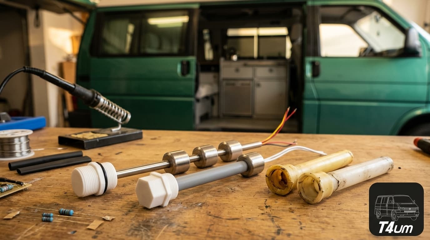
Over the years the original sensors crack, water gets in, the contacts corrode and they stop working. Buying new ones is expensive: on the well-known specialist sites prices are steep, around €100 for the grey water one and up to €600 for the fresh water one. Building them yourself is within reach of anyone with a little skill with a soldering iron and heat-shrink tubing.
Guide based on the post by Peeter on the T4UM forum (original discussion), revised and updated for t4um.it. Thanks to Peeter for sharing the project and the cap files.
How the new sensors are made
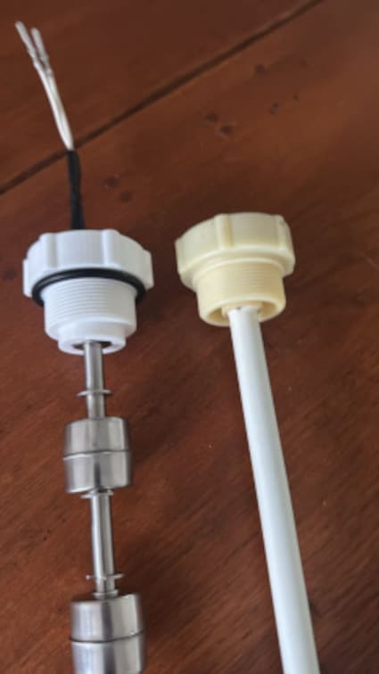
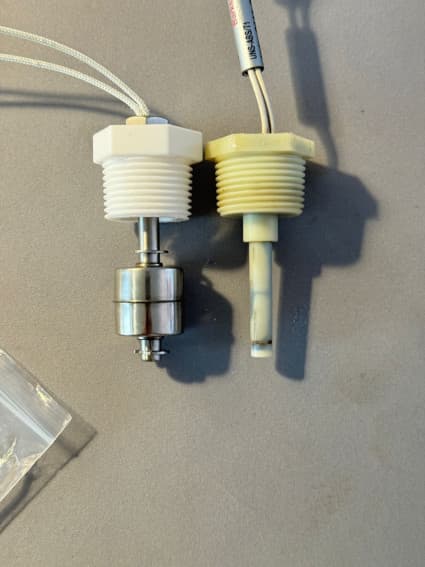
Both consist of a cap designed and 3D-printed for the job and a stainless steel float sensor.
| Sensor | Floats | What it shows on the control panel |
|---|---|---|
| Fresh water | Three | One, two or three bars, depending on how many floats are lifted by the water |
| Grey water | One | Turns the tank-full light on or off (ON/OFF function) |
What you need
| What | Details | Where to find it |
|---|---|---|
| Grey water sensor | Single float, 75 mm long | Amazon (also on AliExpress, for less) |
| Fresh water sensor | Three floats, with three pairs of wires. The 200 mm one was used, because the 300 mm one risked being too long for the tank | AliExpress |
| Resistors | One 680 Ω, one 1 kΩ and one 4.7 kΩ | Any electronics shop |
| 3D-printed caps | One per tank | STL files below |
| Soldering iron and heat-shrink tubing | To join the wires neatly |
On request, AliExpress sellers can make the fresh water sensor to measure, with the floats where you tell them: it costs quite a bit more and delivery takes longer.
STL files for the caps
Grey water sensor
This is the easy one.
- Fit the new sensor to the printed cap.
- Cut the wires of the original sensor, leaving its connector attached.
- Solder the wires with the original connector to those of the new sensor and insulate the joints with heat-shrink tubing.
Fresh water sensor
This one needs a little thought. It has three pairs of wires, and the colour order is not what you would expect:
| Wire pair | Float |
|---|---|
| Black | Bottom |
| Red | Middle |
| Yellow | Top |
For the control panel to light up the right number of bars, the circuit has to return the correct resistance depending on which floats are lifted. That is what the three resistors of 680 Ω, 1 kΩ and 4.7 kΩ are for, wired in series as in the diagram.
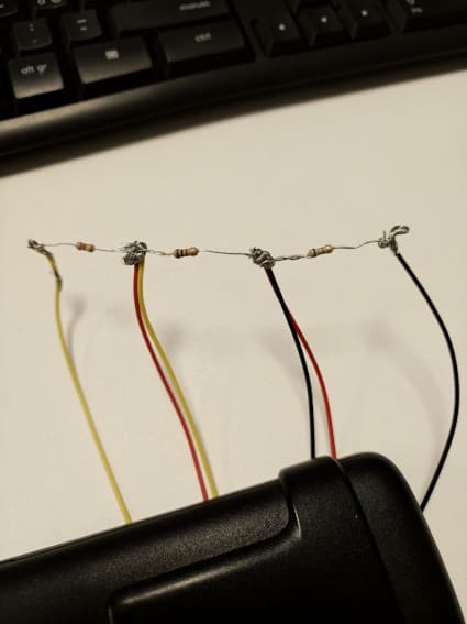
The photo of the layout is only there to show the connections: for a tidy job, solder the resistors and seal them inside heat-shrink tubing. Then, as with the other sensor, cut the wires of the original sensor with their connector and solder them to the new circuit.